Bidirectional visit counter using 8051 Microcontroller
A tally was an ancient memory aid device used to record and document numbers, quantities or messages Historical reference is made by Pliny . The Elder (AD 23-79) about the best wood to use for tallies and by Marco Polo (1254-1324) who mentions the use of the tally in China.
This project is an implementation to the idea of
bidirectional visitor counting and load controlling using a
microcontroller. Currently the main work that has been done on this
proposed system is using ultrasonic sensors which give longer detection
range compared to IR rays. If user wants to switch on and off the
electrical appliances, he/she has to go to a specific area and on /off the
appliance. But in this design, we are controlling the electrical loads remotely
using RF Technology. The user has RF Transmitter and RF receiver is kept
at the application side. The user is able to control the electrical appliances
within the range of 100 feet. We have also used LDR sensor to sense light
condition and depending upon it controls the electrical light loads.
A counter that can change its state in
either direction, under control of an up and down selector input, is known as an up-down counter
. The circuit given here can count numbers of
peoples enter in up and down modes depending upon the state of the selector .
It can be used to count the number of persons entering a hall in the up mode at
entrance gate. In the down mode, it can count the number of persons leaving the
hall by decrementing the count at exit gate. It can also be used at gates of
parking areas and other public places.
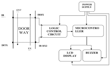
This circuit divided in three parts:
sensor, controller and counter display. The sensor would observe an
interruption and provide an input to the controller which would run the counter
in up/down mode depending upon the selector setting .
INTRODUCTION
This project titled “Microcontroller based Bidirectional Visitor counter” is designed and presented in order to count the visitors of an auditorium, hall, room, offices, malls, sports venue, etc. The system counts both the entering and exiting visitor of the auditorium or hall or other place, where it is placed. Depending upon the interrupt from the sensors, the system identifies the entry and exit of the visitor. On the successful implementation of the system, it displays the number of visitor present in the room. This system can be economically implemented in all the places where the visitors have to be counted and controlled. This system can be used as an automated switch to increase energy efficiency. The system can be used at the entrance of a room to control the light sand other appliances.
Many times we need to monitor the
person/people visiting some people like seminar hall, conference room or
shopping mall or temple. This project can be used to count and display the
number of visitors entering inside any conference room or seminar hall. This is
a bidirectional counter will be increment if person enter the room and
decremented if a person leaves the room. LCD displays this value which is
placed outside the room.
COMPONENT
AT89C51
(8051 based Microcontroller)
8051
Programmer
Push
Button
10µF
Electrolytic Capacitor
2
x 10KΩ Resistors (1/4 Watt)
11.0592
MHz Crystal
2
x 33pF Ceramic Capacitors
16
x 2 LCD Display
10KΩ
Potentiometer
2
x IR Sensors (Reflective Type)
Connecting
Wires
Power
Supply
Keil µVision 5 Software
BLOCK DIAGRAM
 |
CONSTRUCTION
The heart of the circuit design lies in designing the
Microcontroller interface. Here, we used the Microcontroller AT89C51, which is
an 8051 family microcontroller. The microcontroller AT89C51 is interfaced to
the IR sensor pairs at PORT2 pins – P2.0 and P2.1 respectively. The following
image shows the circuit diagram of the Reflective Type IR Sensor Module used in
this project.
The sensor circuit is designed by selecting
appropriate value of resistors for both the LED and the Photo Diode. A 150Ω
current limiting resistor is placed in series with the IR LED. Photo
Diode is connected in reverse bias with a series resistor of 10KΩ. Photo Diode
and 10KΩ Resistor form a potential divider. A 10KΩ POT is
connected at the inverting input. This POT can be adjust in order to change the
sensitivity of the IR Sensor. A 16 x 2 LCD Display is used to display the count
values. The data line of the LCD are connected to PORT1 Pins of the
Microcontroller. The Control Pins i.e. RS, RW and E are tied to P3.6, GND and
P3.7 pins. A 10KΩ POT is connected to contrast adjust pin i.e. Pin 3 of LCD.
Another important aspect of the design involves
designing the oscillator circuit and the reset circuit. The oscillator circuit
is designed by selecting an 11.0592 MHz quartz crystal and two ceramic
capacitors – each 33pF.
The reset circuit is
designed by selecting a resistor of 10KΩ and an electrolyte capacitor of 10µF
to ensure a reset pulse width of 100ms and reset pin voltage drop of 1.2V.
CIRCUIT DIAGRAM

WORKING
When the system is powered ON, the microcontroller initially
initializes the stack pointer and all other variables. It then scans the input
pins (P2.0 and P2.1).In the meantime, when there is no object in front of the
IR Sensors, the light from the IR LED would not fall on the Photo Diode of the
first sensor pair and hence, the Photo Diode doesn’t conduct. As a result, the output of the IR sensors is LOW. In other
words, ports P2.0 and P2.1 are at logic LOW level. If there is a person in
front of the IR Sensors, IR light from the IR LED reflects from the person and
falls on the Photo Diode. As a result, the Photo Diode starts conducting and the output of
the sensor becomes HIGH. In other words, the ports P2.0 and P2.1 are at logic
HIGH level.
Now when a transition takes place, i.e. a logic HIGH level is
received, first at port P2.0 and then at P2.1, the microcontroller sees this as
an interruption to sense the passage or entry of a person or an object in front
of the IR LED and the Photo Diode. As per the program, the count value is
increased and this value is displayed on the 16 x 2 LCD Display.
If the microcontroller senses logic HIGH, first on the P2.1 and
then on P2.0, it assumes that the person is leaving the room and as per the
program, the microcontroller decreases the count as displays the same on the
LCD. The program ensures that the count is increased or decreased only
when both the sensors detect the person.
HOW TO USE KEIL PROGRAM
SOURCE CODE
#include<reg51.h>
sbit sen1=P1^0; //enter
sbit sen2=P1^1; //exit
sbit rs=P1^2;
sbit rw=P1^3;
sbit en=P1^4;
void lcdcmd(unsigned char);
void lcddat(unsigned char);
delay();
void lcddis(unsigned char
*s,unsigned char r);
void lcdconv(unsigned
char);
Void main()
{
unsigned char x,y;
lcdcmd(0x38);
delay();
lcdcmd(0x01);
delay();
lcdcmd(0x10);
delay();
lcdcmd(0x0c);
delay();
lcddis("WELCOME",7);
lcdcmd(0xc0);
delay();
lcddis("VISITOR COUNTER",15);
delay();
lcdcmd(0x01);
delay();
while(1)
{
if(sen1==0)
{
lcdcmd(0x80);
delay();
lcddis("ENTRY:",6);
lcdcmd(0x87);
delay();
x=x+1;
lcdconv(x);
}
if(sen2==0)
{
lcdcmd(0xc0);
lcddis("EXIT:",5);
lcdcmd(0xc6);
delay();
y=y+1;
lcdconv(y);
delay();
}
} }
Void lcdcmd(unsigned char
val)
{
P2=val;
rs=0;
rw=0;
en=1;
delay();
en=0;
}
void lcddat(unsigned char
dat)
{
P2=dat;
rs=1;
rw=0;
en=1;
delay();
en=0;
}
void lcddisp(unsigned char
*s, unsigned char r)
{
unsigned char w;
for(w=0;w<r;w++)
{
lcddat(s[w]);
delay();
}
}
void lcdconv(unsigned char
num)
{
unsigned char p,n:
p=num/10;
n=num%10;
p=p+0x30;
n=n+0x30;
lcddat(p);
lcddat(n);
}
void delay()
{
unsigned int k,l;
for(k=0;k<1000;k++);
for(1=0;1<100;1++);
}
OUTPUT

APPLICATION
- The Bidirectional Visitor Counter using 8051 Microcontroller circuit can be used domestically to get an indication of number of persons entering a party
- It can be used at official meetings.
- It can be used at homes and other places to keep a check on the number of persons entering a secured place.
- It can also be used as
home automation system to ensure energy saving by switching on the loads
and fans only when needed.
RESULT
The final design perspective
as well as highlighting the probable defects engulfing the project . A preview
to the establishes the essence and need for embedded systems towards
technological advancement.
The output of the
receiver circuit sends high or low signal in a form of voltage to the
microcontroller.
CONCLUSION
•
In demonstration of the
project , the infrared sensing part used to detect the passage of visitors
worked.
•
Microcontroller was very
efficient in its task performance, thus computation of counts and controlling
I/O devices.
•
Also, the LCD, led and the
buzzer were effective in alerting and notification
•
Hence the whole purpose of
the bidirectional visitors counter was successfully achieved and is applicable
in the wider scope.
![]()
👍
ReplyDelete👍
ReplyDelete👌🙌
ReplyDelete